
How To Read A Shock Dyno Sheet - A Primer
Compression, rebound, gas force, hysteresis, low speed, high speed, linear, digressive, progressive: What the curve actually tells you about the damper on your car.
Most "dyno data" you'll see from off-the-shelf damper vendors isn't a Force-vs-Velocity plot at all — it's a Peak Velocity Plot (PVP), a single line built from one force number per velocity tested, with everything interesting stripped out: no hysteresis loop, no gas-force offset visible, no cavitation to see, and no Force-vs-Displacement plot at all. If that's the only page you got, you don't have a shock spec sheet; you have marketing.
A real shock dyno run produces two graphs from the same dataset, and each answers a different question. Once you know which is which and what to look for, the "wall of squiggles" turns into the most honest documentation a shock comes with — often the only place a build defect is visible before the shock ends up on the car and confuses you for a season.
One note before we get into it: the curves below are illustrative, not actual pulls off our dyno. This isn't meant to be a deep technical reference or a breakdown of any specific shock — it's a broad overview of how to read the shape of a dyno sheet, and the handful of gotchas we'd personally look for before trusting one.
The two plots
- Force vs. Velocity (F/V) — how much force the damper makes at every shaft speed. This is the tune: how stiff, where in the speed range, and how it's split between bump and rebound.
- Force vs. Displacement (F/D) — how force is distributed across the shock's stroke. This is the health: gas pressure, cavitation, build issues, whether the internals are actually doing what the drawing said they would.
Most vendors ship one and hide the other — or worse, ship only the PVP described above and call it F/V, which obscures exactly the information you'd want the dyno for in the first place. More on that below. If your vendor doesn't ship the full traces, ask. If they can't, buy your dampers somewhere else.
There's a third thing the sheet tells you, on top of whether the shock is healthy and whether it's built well: whether the damping itself is actually suited to what you're doing with the car, and sensibly matched to the spring rates it's paired with. A shock can be flawless by every build-quality measure — clean loops, correct gas charge, nothing cavitating anywhere — and still be the wrong shock, because a digressive curve, a linear one, and a progressive one (more on this below) aren't interchangeable, and a curve tuned around one spring rate can feel completely wrong bolted behind another.
That said, this leaves out other core parts of getting a shock right — mounting geometry and the shock's own dimensioning, shaft length, stroke, body size, all the things that determine whether a shock is even physically and kinematically correct for the car it's going on. None of that shows up on a dyno sheet at all. It's also worth knowing that a lot of marketing-forward shock builders will happily sell you the same dimensioned shock with the same valving regardless of what you tell them the car is doing, what springs rates you're targeting, etc. Adjusters can change the shock in some ways, but how they do so is very situational, frequently won't do what you expect them to do, and they are drastically less powerful than getting the valving right. I'd trade adjusters for quality valving 100 times out of 100.
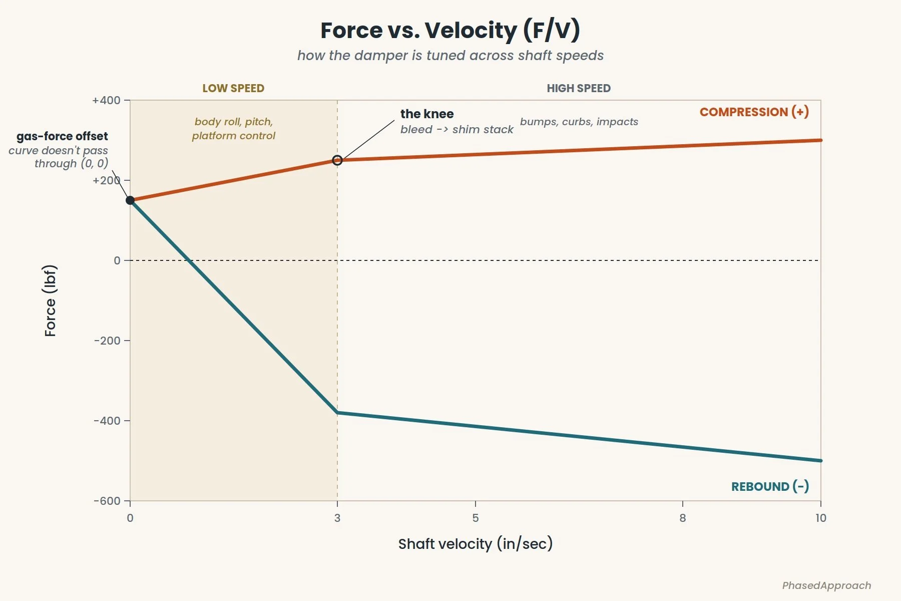
A sample, simplified F/V plot.
Reading the F/V plot
Force vs. Velocity with the landmarks worth naming.
The plot's convention is compression on top, rebound on bottom, shaft velocity on the X axis as a positive number regardless of direction. Compression is the half of the cycle where the shock is shortening — wheel moving up relative to the chassis. Rebound is the shock extending, wheel moving down. They are two independent damping circuits sharing a housing, tuned separately, and the sheet is where you find out whether the build actually matches the intent.
The knee. Somewhere between roughly 2 and 4 in/sec on most road-going dampers there's a visible inflection where the slope changes — steep below, shallower above. It isn't the damper "deciding" anything; it's a hard change in the flow path. Below the knee, fluid moves through small, restrictive bleeds — adjuster needles, fixed orifices — so force ramps up sharply with velocity. Above the knee, pressure has deflected the piston's shim stack far enough to open a much larger port area, and the force-vs-velocity slope drops off.
That transition doesn't have to be abrupt, and on the better dampers it isn't. A hard, sudden knee means the tire sees a step change in damping force the instant the shaft crosses that velocity — which shows up at the contact patch as a sudden jump in load rather than a gradual one, and on an inconsistent surface, as a car that feels like it's reacting differently depending on which side of that threshold the last bump happened to land on. A well-designed piston and stack blend the transition instead of snapping through it, so the curve bends smoothly rather than kinking, and the tire's load stays more predictable across a wider range of inputs. If the knee on a sheet looks like a dogleg — two straight lines meeting at a sharp corner — that's not automatically wrong, but it's a design choice, and not always a good one on rough or variable surfaces where the shaft is crossing that velocity constantly.
This is where it shows up most obviously in practice: go from a low-grip session — cold, damp, slick asphalt — to something abrasive like concrete, and a car with a sharp knee can feel like a different animal from one session to the next, because the shaft is now spending its time on the other side of that threshold. That's a great way to end up chasing knobs at every session instead of trusting the car. The fix isn't a bigger adjustment range; it's a curve shaped so the car's motions stay controlled across the whole velocity range the shock actually sees, rather than getting handed off abruptly from one circuit to the other depending on how fast the shaft happens to be moving that lap.
This split matters because it maps directly to what you feel on the car:
- Low-speed damping (below the knee, roughly 0-3 in/sec) is what you feel almost every second the car is moving — body roll buildup, pitch under braking and throttle, ride-height management in steady-state cornering. Set by the bleed circuit and by how stiffly the shim stack initially resists deflection.
- High-speed damping (above the knee) is what takes over when the wheel gets hit with something sudden — a bump, a curb, a pothole. It's set by how stiff the shim stack is once the piston has fully opened up.
This is also why the two adjusters on a typical coilover work the way they do. "Low-speed" clicks move a needle in or out of the bleed circuit — they shift the low-speed slope and pull the knee location around, but they barely touch the high-speed slope. "High-speed" clicks, if the damper has them, preload or unload the shim stack itself, moving the above-knee line. A click of low-speed compression will change how the car feels at turn-in and nothing about how it handles big bumps. If someone tells you otherwise, ask them where the knee is on their dyno sheet.
It's worth being skeptical here in practice, because what you think an adjuster is doing and what it's actually doing on the sheet are frequently two different things. The common version: you add low-speed compression to load the tire faster and pick up some platform support, which is the intended effect — but the secondary effect is a knee that's moved and sharpened more than expected, with the high-speed line creeping up right along with it because the adjuster wasn't as isolated from the shim stack as the marketing implied. At that point the click has stopped being a platform-support knob; it's a blunt instrument that stiffens the whole curve, closer to a tire-volume knob than a damping adjustment, and the car just rides worse without giving you the specific effect you went looking for. The only way to know which one you're actually turning is to look at the sheet across a couple of clicks, not just read the label next to the knob.
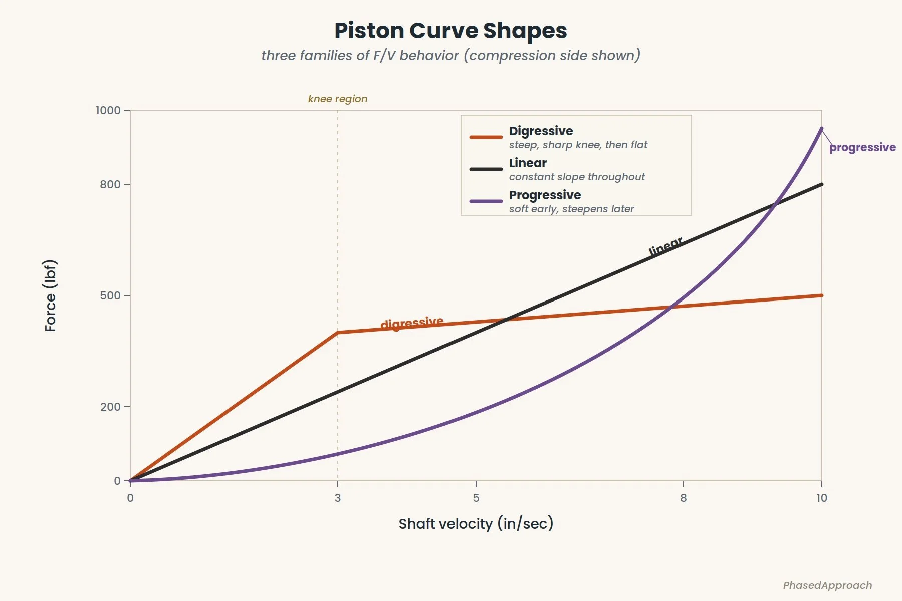
Curve shape above the knee: what the piston is doing
The shape above the knee is set primarily by the piston design and the shim stack behind it, and it lives in one of three families:
- Digressive — steep low-speed slope, sharp knee, nearly flat above. Lots of platform control at low speeds, then a "blow-off" that lets the wheel move freely over impacts. Common in autocross and short-course, where discipline in the low-speed range matters more than bump absorption. Easy to overdo — too aggressive a blow-off and the chassis feels disconnected from the wheel above the knee.
- Linear — constant slope through the whole velocity range. Predictable, easy to model, the default of a lot of OE and entry-level aftermarket. No character, no surprises. Perfectly reasonable for a lot of cars.
- Progressive — soft low-speed, steeper at higher velocities. Compliant on small inputs, firmer the harder the wheel is hit. Useful in rally and rough-road contexts. Unusual in pavement motorsport, because on pavement you generally want the damper to get out of the way above the knee, not bite harder.
When a vendor describes a piston as "digressive," this is what they mean, and the sheet is where you check them. If the piston is marketed as digressive and the curve above the knee is a nearly straight line, either the word is being used loosely or the stack — not the piston port — is doing all the work. Both are worth a question.
Gas force
Most dampers carry a charge of pressurized nitrogen behind a floating piston, which keeps the oil from foaming under quick movement. That charge also pushes the shaft outward with a small, constant force even when the shock isn't moving at all — which is why the curve doesn't start at zero on either plot, but sits offset above it by a consistent amount. It isn't damping, and it barely matters once things speed up; the only real question is whether the build hit the pressure it was designed for. Too low, and you're headed for cavitation. Too high, and you've added preload that the rest of the setup now has to account for.
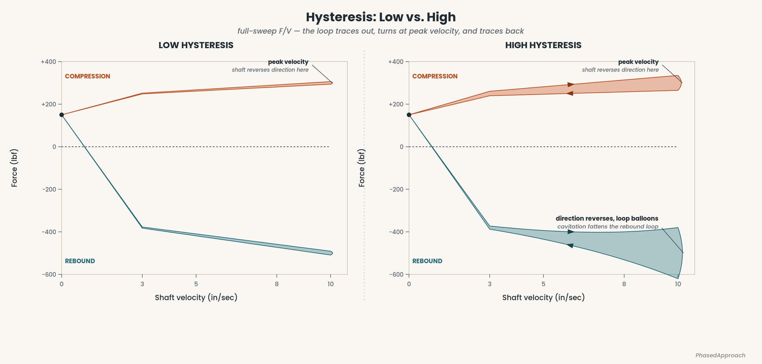
Low and high hysteresis in an F/V plot.
Hysteresis
Hysteresis is the loop the trace makes over a complete cycle. The damper produces slightly different force while it's accelerating toward a velocity than while it's decelerating away from it — seal drag, oil compressibility, and shim-stack settling time all conspire — so what a textbook draws as a single line is in reality a thin loop. The width of the loop is the hysteresis, and it is the single most useful diagnostic on the whole sheet.
Less is better, plain and simple. A thin, tight loop means the damper is doing close to the same thing whether it's accelerating or decelerating through a given velocity; a fat one means it isn't, and the wider it gets, the more the actual force at any instant depends on which direction the shaft was headed when you caught it.
Why does loop width matter beyond being a diagnostic? Because it's a direct measure of how far the damper's actual force strays from its intended force at any given instant — and that gap doesn't average out, it shows up as inconsistency the driver feels but can't name. A damper with a fat loop doesn't behave like a softer or stiffer version of the same tune; it behaves like a tune that changes slightly depending on whether the wheel is speeding up or slowing down through that velocity, which is a much harder thing to trust on track. Eliminating it is mostly a build-quality problem rather than a design one: clean, well-toleranced seals and bores so friction is low and consistent, properly degassed oil so there's no entrained air to compress, a gas charge held comfortably above the cavitation threshold at the velocities the car will actually see, and a shim stack that responds quickly. None of that is visible in a single force-per-velocity number — it only shows up as a shape, over a full cycle, which is exactly why a sheet that hides the loop is hiding the main way a bad build gives itself away.
None of this tracks with price or reputation the way people tend to assume. Hysteresis is fundamentally a hardware and process problem — seal material and cross-section, bore tolerance and surface finish, how consistently the gas charge and fluid fill get done from unit to unit — and a recognizable name or a premium price tag doesn't guarantee any of that was done well.
This is honestly one of the biggest real differences between a lower-quality brand and a higher-quality one, probably more than any other single line item on the sheet. Penske is the gold standard the rest of the industry gets measured against here — their hysteresis is close to negligible, pull after pull, and it's a real part of why they cost what they cost. The encouraging half of this is that very low hysteresis doesn't require exotic hardware; a well-considered build on modest components can get impressively close. The discouraging half is that we've put plenty of expensive shocks on our own dyno with genuinely unacceptable hysteresis, price tag notwithstanding. Without a full F/V trace you'll never see it on paper. On the car, you'll feel it — you just won't necessarily know what to call it.
Why the PVP is dangerous: the PVP throws the loop away. It draws one line through the middle of each cycle and calls it done. Cavitation, seal drag, build defects, none of it appears. You can buy a brand-new shock with a "passing" PVP and a clearly cavitating F/V trace, and the PVP will never tell you. This is why we ship the full trace on every damper we build, and why you should insist on the same from anyone else you're paying.
That same argument extends past a single dyno pull. Hysteresis grows with the force the damper is producing — more force means more energy moving through the seals, the oil, and the stack per cycle, so the loop widens as you climb the adjustment range. On a good shock, it widens proportionally: the stiffest click has the widest loop, but it's still a thin, clean band. On a lesser shock, the loop grows faster than the force does, and the top of the adjustment range is where the damper falls apart — often while the softer settings still look perfectly respectable.
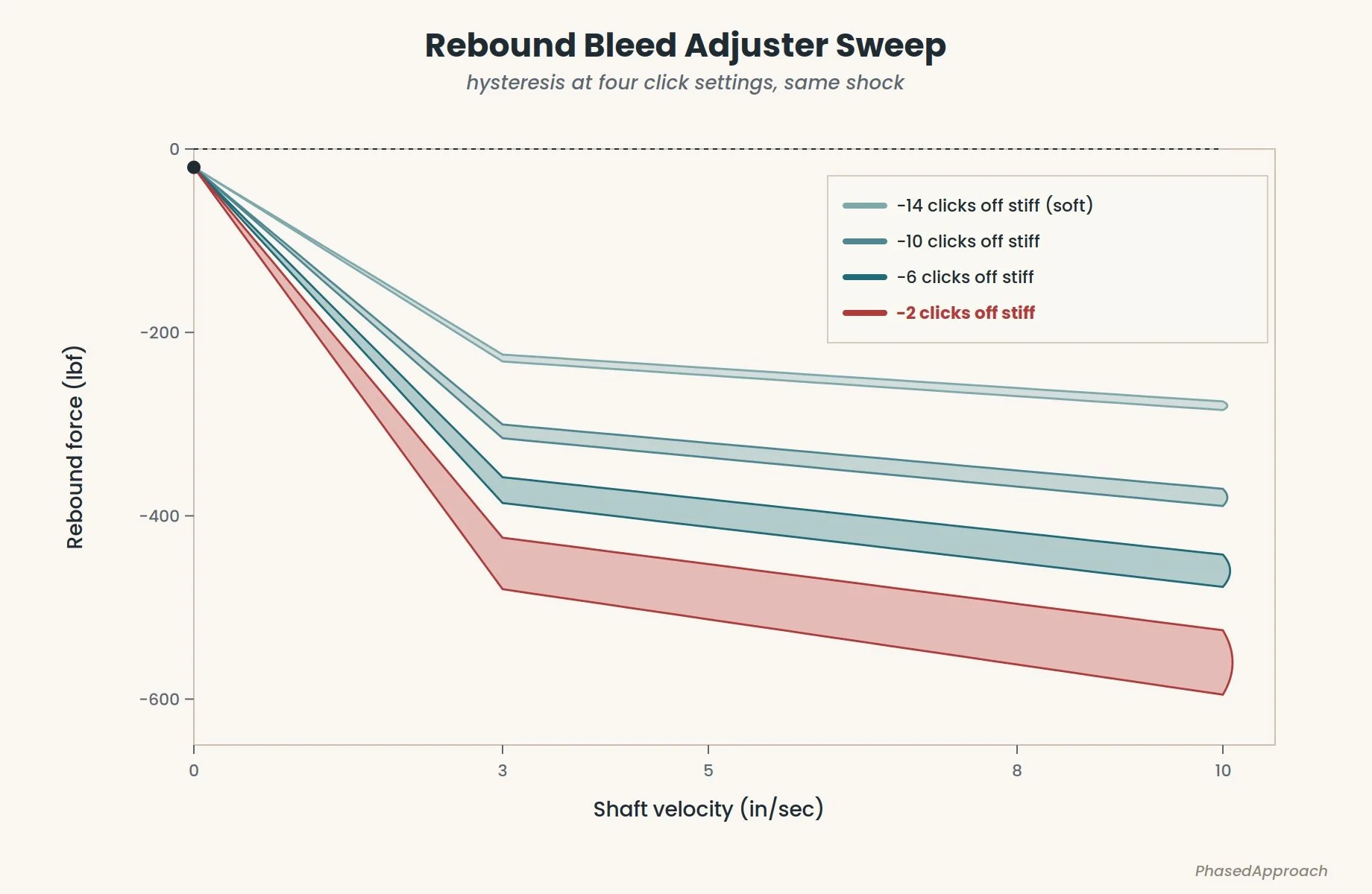
Same shock, same gas charge, four different settings of rebound bleed. Loop width grows with force at every setting — and on this shock it blows out disproportionately at the stiff end of the range.
If a vendor's spec sheet shows one click position and calls it representative, that's the PVP problem all over again, just spread across the adjuster instead of across velocity. And it's usually the flattering click — the middle of the range, where forces are moderate and the loop is naturally thin. A shock that looks clean at -10 clicks off stiff and cavitates at -2 isn't a clean shock; it's a shock you can't actually use near the top of its range, which is exactly where you were counting on it. The only way to know is to see fairly complete sweeps of the adjustment range — both to evaluate whether the shock is any good, and to know which parts of its range you can trust once it's on the car.

Reading the F/D plot
The F/D plot is the same data plotted against shaft position instead of velocity. The typical shape is a roughly oval closed loop, lopsided in the direction of whichever side of the damper is doing more work. Reading it takes a second of orientation:
- The ends of the stroke are zero velocity — force at the ends is gas force plus any end-of-stroke effects (bump stops, hydraulic top-out, and so on).
- The middle of the stroke is peak velocity for a sinusoidal dyno motion, and therefore peak damping force. Top of the loop is peak compression; bottom is peak rebound.
- Anything unexpected is a flag — a divot, a notch, a step, a slope discontinuity mid-stroke. The damper should produce smooth, continuous force through the stroke. Discontinuities mean something mechanical is happening as the piston moves through a specific position: a port being uncovered, a piston band stepping over an edge, a check valve chattering.
The short version: The F/V plot is the tune — compression up, rebound down, low-speed under the knee, high-speed above, and the curve shape (digressive, linear, or progressive) tells you what the piston-and-stack combination is trying to do. The F/D plot is the health — a clean, symmetric loop offset upward by the gas force is what you want to see; a missing offset, cavitation-shaped fat spots on velocity peaks, or discontinuities mid-stroke are all problems the PVP will happily hide from you. Every PhasedApproach customer gets both, plotted in full, in the Dyno Viewer — because it's the documentation you're actually paying for.
One honest caveat: this is a primer on reading the sheet, not a treatise on what the numbers should be. We've simplified plenty here — spring rate interaction, unsprung mass, motion ratio at the wheel, the difference between what a dyno shows at the shaft and what actually happens at the contact patch, none of that is in this article. Damping's effect on vehicle dynamics is a much deeper rabbit hole than "read the squiggles correctly," and we're barely past the front door of it. If this gets you to the point where you can look at a sheet and know what you're looking at instead of nodding along, it's done its job.